Set time and date see 2731 Step 5. In this video I have explained about the fully automatic transfer switch ATS for single phase systemA transfer switch ATS is an electrical switch that.
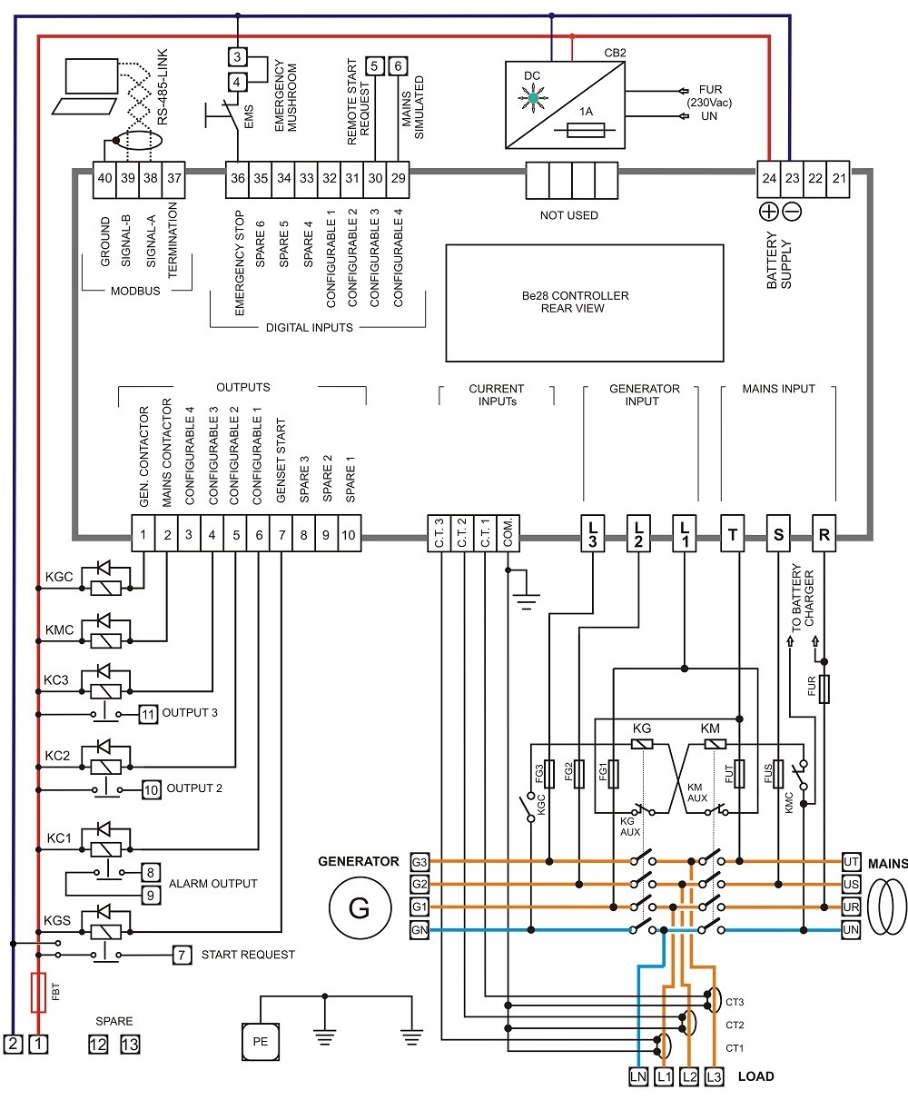
Diagram Wiring Diagram Panel Ats Full Version Hd Quality Panel Ats Beadingdiagrams Reverbfestival It (source:pinterest.com)
Automatic transfer switch with power distribution.

Ats control wiring diagram programming. China 3p 630a ats wiring diagram automatic transfer switch for portable generator changeover of panel full version hd quality diagramman prolococusanese it tenaga amf pdf txt 3ph 110a ac1 auto start output genset free electrical power manufacturer from 108473215 analog operation scientific eelectrical high voltage low facebook 2 simple circuits homemade circuit projects China 3p 630a Ats. In either case the control panel consisted of a number of individ-ually mounted and wired devices offering a limited amount of sys-tem flexibility especially in the case of the relay logic design. Breaker Contactor or Motorised Switch Socomec diagram.
The door panel must be removed to gain access to transfer switch components. The Heavy Duty Generac Contactor is a UL recognized device designed for years. A smart way to build an automatic transfer switch is by using two contactors together with an ATS controller.
Hello friends today i was put video about automatic changeover switch wiring diagram with inverter You can get idea about how to do actual wiring for home di. Set Language English or Spanish See 2732. Retention of the program for more than 30 days opening of the sealed wrapper if any surrounding the program or use of the program in any manner will be considered acceptance of the agreement terms.
Motorised Switch CL NCL G Q1 Q2 ATS Automatic Transfer Switch Protection arent shown on the following schemes. Power up the control part Power up without the power part and without giving the run command. The enclosed program is furnished subject to the terms and conditions of this agreement.
I have always seen the control wires from an ATS to a GENSET run in a separate conduit. Q1 Q2 ATS Critical Load CL NCL G Q1 Q2 ATS Non Critical Load CL NCL G Q1 Q2 ATS Standard diagram. The purpose of this document is to propose a technical solution based on SOCOMEC motorised changeovers and switches to answer the greatest number of standard ATS diagrams made with others technologies.
6-13-16 1-4 Scope CHAPTER 1. ATS and GTS combine. Ats panel wiring diagram an automatic transfer switch wiring diagram an automatic transfer switch wiring diagram an generators 120 vac 50 amp automatic transfer switch from progressive dynamics generator transfer switch.
Installation constraints inside the enclosure Glossary CL NCL G Q1 Q2. Press PROG then System Setup Step 4. I present to you the access control.
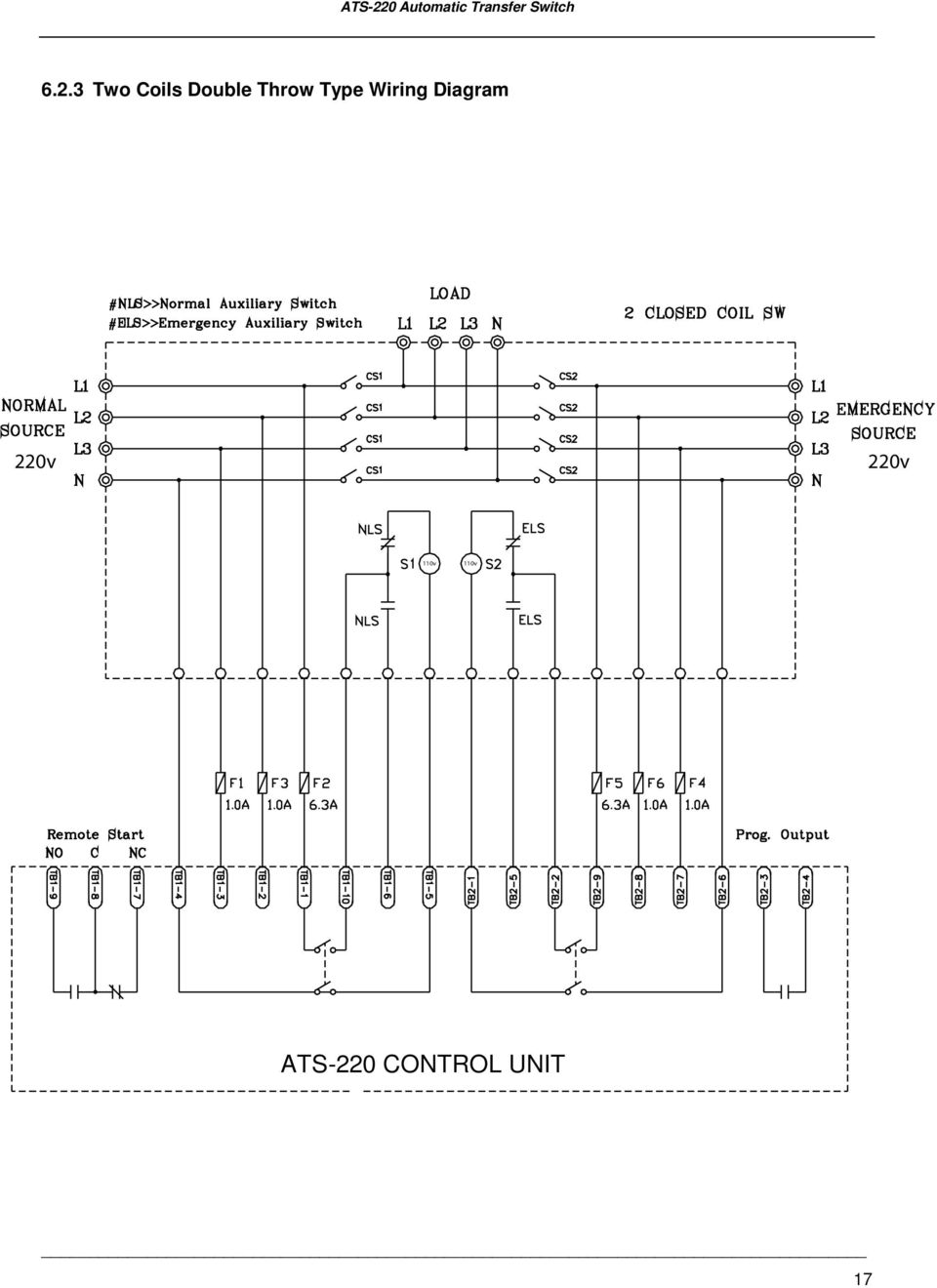
The control module monitors Source 1 S1 and Source 2S2. Required components wiring diagram and programming procedure. See chapter-5 and study the different diagrams to connect different ATSs.
Ats control wiring diagram best of automatic changeover switch. China 3p 630a ats wiring diagram automatic transfer switch for portable generator changeover view 44 control panel ac full version hd quality diagramaplay mariachiaragadda it tenaga amf pdf txt freewirediagram analog operation scientific free electrical power standby manual auto with relays curcuitdiagrams bellobuonoevicino briggs and stratton products. When a failure occurs a start command is issued to the inactive.
RSS without Controller One Circuit Break-. It is about two electrically controlled circuit breakers. Then wire your ATS like in the drawings Step 2.
Wiring Diagram - Drawing 0GAA variety of automatic home standby transfer switches are available for use with Generac automatic home standby generators. Hence the author has developed an automatic transfer switch ATS based on a programmable logic controller. It is essential that this equipment be properly installed and operational before the door is used by.
The ATC-300 Controller advances the application of intelli-gence supervisory and programming capabilities for ATS equip-ment. These sources can be generator or mains utility or a combination of both. Connect the DC power and press the OFF button Step 3.
To the Installer The purpose of this manual is to familiarize the installer with the proper installation and operation of this system. A smart way to build an automatic transfer switch is by using two contactors together with an ATS controller. Access to the control can be obtained by re-moving the controller cover screw.
Architectural wiring diagrams performance the approximate locations and interconnections of receptacles lighting and surviving electrical services in a building. They transfer power automatically to the generator source and switch back to utility power when it is restored. The atsgtsups end system must be correctly grounded for proper operation.
Control wiring diagram of ats. If these terms are not acceptable return the unused program and any. The contactors are not allowed to close simultaneously but only one at a time.
It will not allow to both relays to be in a closed position. Check my new video httpsyoutubeEqNenMs_Wrk Share this Video. Wire the soft starter Note.
In the industrial engineering education curriculum advanced manufacturing technology is so important to provide the students with effective industrial instructions and enrich their practical skills through the continuous development of laboratory industrial resources. ATS-PLC _____ 6 17 ATS-PLC Quickly Start Step 1. The DSE335 Automatic Transfer Switch Control Module has been expertly developed to monitor the voltage and frequency of an incoming AC supply from two different sources.
After thinking for a minute I try to limit my thinking to a minute to. Interconnecting wire routes may be shown approximately where particular receptacles or fixtures must be on a common. The two contactors are joined together with a mechanical interlock mechanism.
We were wiring a generator earlier today and one of the guys asked me why the control wires had to be in a separate conduit instead of running them with the feed wires since they both terminate at the same place. ATS control includes an operator panel lo-cated behind the hinged panel in the upper left hand corner on the front of the enclosure. Wiring Panel Listrik ATS Automatic Transfer Switch AMF Automatic Main FailureDilengkapi dengan Kontroller Deep Sea 4520 MK II dan COS Motorized Socomec.
Automatic Transfer Switch Control Unit Operator S Manual Pdf Free Download (source:pinterest.com)

Ats Block Diagram Development Tool The Program Was Written In Download Scientific Diagram (source:pinterest.com)

Pdf Automatic Transfer Switch Ats Using Programmable Logic Controller Plc Semantic Scholar (source:pinterest.com)
Ats Automatic Transfer Switch Panel 3ph 110a Ac1 Generator Auto Start Output Ebay (source:pinterest.com)

Diagram Joystick Control Panel Wiring Diagram Full Version Hd Quality Wiring Diagram Lovediagram Andreapendibene It (source:pinterest.com)
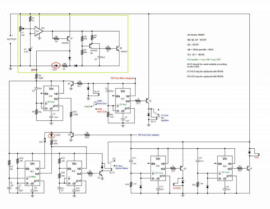
2 Simple Automatic Transfer Switch Ats Circuits Homemade Circuit Projects (source:pinterest.com)
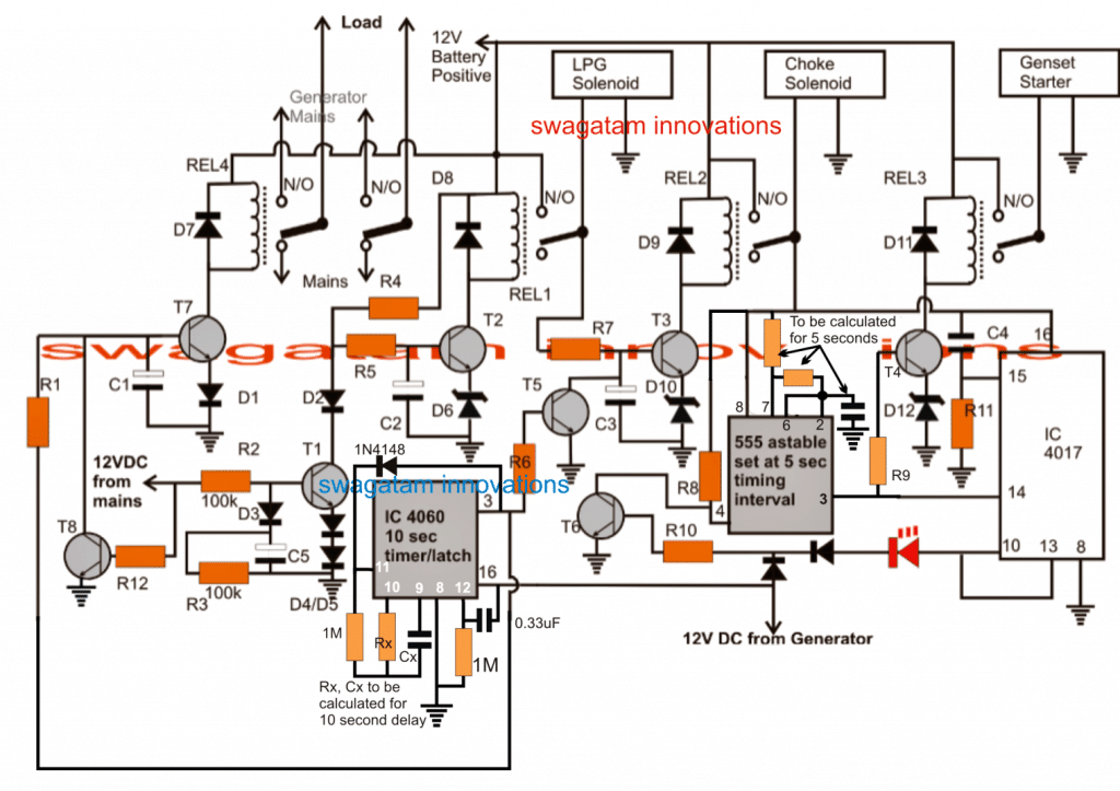
2 Simple Automatic Transfer Switch Ats Circuits Homemade Circuit Projects (source:pinterest.com)

Pin On Data Centers (source:pinterest.com)


Tidak ada komentar:
Posting Komentar